Landing gear handle

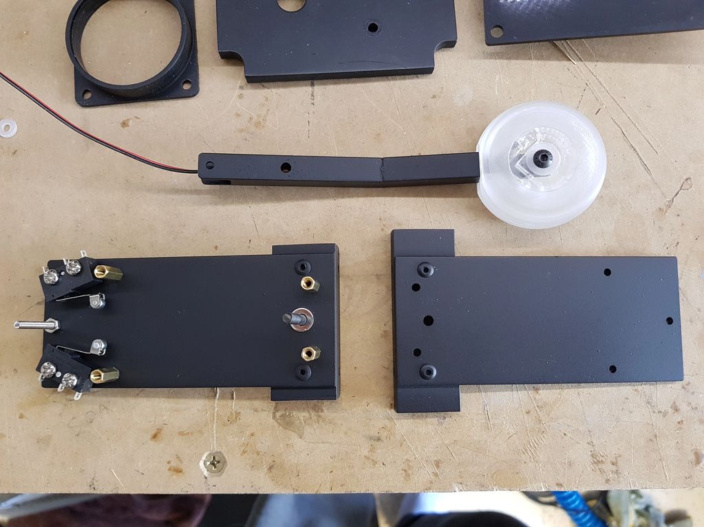
This photo shows the landing gear assembly. It is a sandwich of two pieces of aluminum stock, riveted to some aluminium L profile so it can be bolted tp the back of the panel. The sandwich is held together with brass standoffs and screws. Two microswitches for the electronics, and the RC car shock absorber acts as a fulcrum to keep it in either position and give it a nice firm clunk.

The other side of the landing gear assembly bolted together, minus the handle. The lever is Aluminium U channel, with the opening on the bottom where it can not be seen.

Landing Gear assembly painted up before final assembly. The handle is layers of laser cut acrylic. To smooth out and round the edges I put a bolt through the centre, clamped it in the chuck of a power drill like a lathe and smoothed it with some sandpaper. The wire is connected to two 5mm red LEDs that illuminate on gear movement.

Assembled. As seen it is a simple design. The RC shock absorber works great and gives it a real tactile feel and a nice solid home position. The brass standoffs that hold the parts together also act as a way to limit the movement of the lever.

A look down into the Landing gear sandwich. The Aluminum L profile riveted to the front can be seen. It has holes drilled in to the front where it bolts to the rear of the panel.

The finished assembly. The wire for the LED's is connected to an Arduino Uno behind the panel that illumunates the LEDs in the handle.
Fire Handles

The fire Handles were designed and built before I had access to a 3D printed. I laser cut the assembly out of 3mm acrylic, then glued it all together using a solvent cement.

Fire Handle assembled.

The three fires handles assembled. The clear front part is acrylic, and the text is reverse engraved into the back of it. I then painted the text black by hand with a paint brush. A translucent white peice is then behind it.

The mechaninsm is very simple. 10mm diameter aluminum dowel in a laser cut acrylic bracket. It is retained by a single bolt thatslides in a slot in the plastic. A micro switch (not pictured) is pressed by the bolt when it is pulled outwards.


Fire handles illumuninated. There is a small section of yellow LED strip lighting behind inside. Because it is 12V LED strip I couldnt run it direct from an Arduino, so there is three relays behind the Main Instrumet Panel.
fuel panel lever

The fuel lever was designed, printed and very kindly given to me for free by ED forum user Blue73, an absolute legend. It is designed to be mounted on a potentiometer, so it can be used as an analog axis. I used the pot as an axis only, its not connected to anything. The two microswicthes open and close it.

3D printed handle in place on the panel. Looks heaps better than the simple aluminium rod i had originally hanging out of it.